Showing posts with label sovereign. Show all posts

Friday, 16 January 2015

Tower Block

I believe that I've stated in previous posts that we have a 3D library in which we import our equipment and buildings. We have been in need of a tower block for the library and below you can see the tower block that I created. This was a rather simple building to create as it just involved mirroring and copying. 
To create, I simply created one half of the first floor, mirrored it, then copied it eleven times to create twelve floors. The ground floor and top floor just had extruded polys added to them along with details such as the door and aerials on top. 


Thursday, 8 January 2015

New School 3D Renders

I managed to have time today to complete my 3D school model. With the previous renders, I was pleased with how they came out, however, I felt that they could of been more realistic. So with that in mind, I added windows to the gabale of the main roofs, added in more walls, a road way out the front, trees, ramps, playground markings and a tower. By doing this, I have added realism to the renders which is what I wanted to do to improve them. 

To add the windows, I simply inserted cuts to the gabale's to extrude into the wall, then build the window and slot it in. The things such as equipment, roadway and trees were imported in from the library.


Monday, 5 January 2015

3D Process

So its now the new year and due to our busy period before Christmas, we haven't been as busy which is nice. However, during today, I drew up a job then created the 3D for it as well. You can see the file drawing below and to be honest, it was a bit of a mess. However, I eventually drew it up as and completed the 3D


To the left you can see the completed 2D of the area with all equipment and surfacing added in. After doing that, I paste the 2D into another Turbo Cad doc. and create a basic dwg. file, ready to import into 'Autodesk 3ds max 2012 64 - bit', to create the 3D. 


When the dwg. is imported into 3ds max, and after selecting the right scale (meters), every thing is ready to start building. We are lucky enough to have a library in which equipment is already made, and its just a matter of importing them in to the model and moving it around. With surfacing, its very simple as you just add the correct textures to plains and if its safety surfacing, you add the depth. 


This was a fairly simple area to 3D as it only consisted of a tower, planter, shading, play kitchen,  mound and surfacing. After adding in the equipment, I ran a quick test render to make sure that the textures were all okay, this is because sometimes the names of textures duplicate and cause errors on other pieces of equipment; for example, sometimes you can have a child with a complete grass texture on them... I then created the surrounding area by viewing the photos that the rep provided; that is just usually trees, school buildings and surfacing. Finally, I add the cameras which the render will view from and then render.


Here are the complete renders of the 3D

Render One
Render Two
Render Three

Tuesday, 23 December 2014

3D School Complete Renders

So after completing every thing yesterday, this morning when I came in, to complete every thing, I just had to hit render and here are the finished results. I am actually pretty pleased with how the renders came out; however, the only issues for me are the fact that I haven't added any windows to the larger front walls of the roofs. Also, I could of gone into more detail designing a car park and created a road for the front of the school. The school its self could have had some planters and play equipment added to add some extra realism and detail. These are some things that I will definitely change and add in the new year!


Monday, 22 December 2014

3D School

Luckily, its the 22nd and we've only got 2 days left until the Christmas break. Last week was super busy, however its gone pretty quiet for these last few days. So I was tasked with creating a 3D of a school building that could be used within the library. To start of with, I simply went on Google images to find an image of a school that I could roughly base my model on and after finding one, I got to work with the bases of the school. To create it, it was just a matter of creating cubes and adding cuts so I could manipulate the shape by using tool such as; bevel, extrude and shamfer. To create the roofs, again, I simply used a cube and dragged the corners to create the roof like shape. Then just added the correct textures to the different plains of the shape. Like the rest of the building, windows and doors are very easy to create. Its just adding cuts and extruding them, then adding textures. 

Whilst creating the 3D, I took photos with my phone so you can have a rough idea of the process that I undertook. The reason the building being multicolored in the photos is so that I could decipher the different polys.   


The model is now ready to render which I will do tomorrow in the morning when I first come into work.


Friday, 19 December 2014

The Weeks Work Load (Progression)

At the end of November, I said that I wanted to set a target to match a full designers rating. As its the week before Christmas, this means the schools/clients will want work to start over the school holidays, basically meaning that before school holidays, its our extreme busy periods.
So I thought I would write a quick post about this weeks work load in regards to my target.

You can see below the complete rating for Monday this week, and with a rating of 5, I am pretty much meeting my target. You can also see that I am up there with the other full designers!

Totals for the day

At the end of this week, I drew a total of 21 files, and once again meeting my target. You can see this below as I use a chart to track my work load throughout the week. I am able to write on the rating of the file, its completion date, if I've completed it and when its been signed of.


Monday, 8 December 2014

2D Special Product

Some times, we have special products be requested for order and below is an example of a most recent one I've had to create. This was a rather simple one to do and took hardly any time at all, but i thought it would be a good example as I can show the process with out it becoming to confusing.

Below is a 2D drawing of a 'Fox Tail Tower', one of our products which consists on a 1 meter high tower deck, slide, rock climber and fireman's pole. The red and blue perimeter are the fall zones and show the maximum and minimum fall zones. 


For this product, I had to change the fireman's pole to a log ramp. Below is an image that shows all the available equipment attachments depending on the height of the deck.


Here is an image of the tower exploded ready for the new piece of equipment to be added.


This is the tower design completed, as I said, this was very simple to do as it was only changing one thing. Reps can as for pretty much any thing the want (within reason). For example, I recently had to design a tower with 3 decks, 2 slides and lots of other equipment.


After completing the design of the custom product, if its a tower, you have to consider the safety fall zone area. This is showing the amount of fall zone area and takes into consideration how much safety surfacing that you need to meet 'BSEN Safety Standards'. Below is our fall zone template in which we use to work out the fall zones.


Here below, you can see the correct fall zone template to work out the maximum fall zone line. 


After drawing the maximum fall zone line, we have to use the same fall zone templates, but go in 0.35m form the attachment equipment due to its steep angle. This then creates the minimum fall zone line. 


Below is the complete 'Custom Fox Tail Tower' with a log ramp instead of a fireman's pole. This will then be used on the design and will need to have its own separate quote created using each of its parts. 


Tuesday, 2 December 2014

Drawing the 2D of an area

Last week I wrote a post explaining what I actually do at work and what a typical file consists of and what I have to do. Today I though I could show you in more detail how I go about drawing up an area that I am presented with.

So as you can see to the left below, we have the file with the drawing of the area that the rep drew at site. The reps usually draws the area to a 1 or 2 meter square scale (on square boxed paper) with the measurements to the side of the drawing. Using 'TurboCAD Professional 17', I then draw out the measurements as a template for me to draw up the area. By doing this, it allows me to double check all the measurements and insure that every thing is perfect. Some times the Reps measurements might not add up and this requires us to either send an email or call them to fix the problem. Some times the drawing can be quite large and if its to scale, I scan the drawing into the back view port, scale the drawing, check the measurements, then simply draw over the lines of the drawing. However this example file was an easy area and didn't require me to do it.

Using the measurements, and straight lines, I am then able to start drawing and building up the area going of the drawing from the Rep. After drawing all the main lines, I then start to add detail to the drawing, for example; windows, doors, fences, gates, buildings, sheds, slopes, the fall of the area etc.


After doing that, its then just a matter of adding in the colours to make the area look presentable to the client, and obviously represent the area I am designing. To do this, we have a swatches section on the side of the design view port. It has things such as surfacing, wetpour, mulch and other basic things like trees and doors. Like I said earlier on, this design was rather simple to do and to the bottom left, you can see the finished area. The next stage is to then add the equipment that the rep asked for. However, I'll show you how to do this within another post.


Sunday, 30 November 2014

Managing Time And Efficiency

Although most people would think that designing is the main part of my job/apprenticeship, another main thing within my job role is managing my time and efficiency. Whilst drawing up files, it requires us to work at a high pace to get jobs completed by a required date, some times the same day. We have to do this whilst making sure that the designs them self are perfect with no errors. 

There are a number of ways in which we as a team within the design department make sure there are no errors with one another's work. To prevent errors in our work, then means that we all look better, but also we don't waste time correcting the errors at a later date, thus resulting in the fact that we are managing our time efficiently! 


To prevent errors within our department:

Whilst drawing a file, I make sure that I double check every thing; for example, the measurements of the existing area, the correct surfacing and equipment going in. Also as I'm only an apprentice designer, I like to ask questions to my trainer to ensure that every thing is correct. 
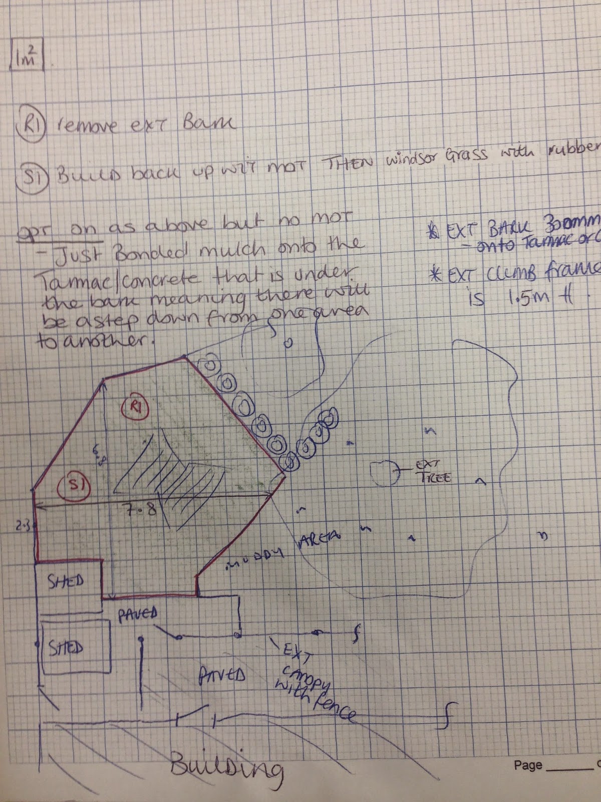
When checking measurements, I draw the base of the area and visually show all the measurements on the drawing so I 100% know that there are no errors with the design. I will show this on a post blog when I present an example area of a 2D drawing that I have drawn up for a file. 
Sometimes, when drawing a file, errors occur that the reps have made themselves. In this case, we have to email the reps for confirmation, and once they reply with the correct answer, thus means its perfect. 
After completing a file, we do something called a peer assessment. This involves giving the design file to another full designer to check over. This means that they can find errors that you wouldn't see. After doing this, we then give the file to our manager Holly, who then does a final check of the file before sending it out to the client.
Peer checks happen between the full designers, due to my level as a designer apprentice, I am not able to check full designers work, simply because I don't have the knowledge yet. However, there are currently three apprentices within our design department and after drawing a file, we all check each others work; this then allows us to each learn how to check work, find mistakes and sometimes learn things that we didn't know before. 

If I do happen to make errors within my work, these are some of the consequences that could happen:

I would waste time correcting the error when I could be in fact working on another file. This could then result in the job going out late, meaning an unsatisfied client.
If I made a mistake with the equipment or surfacing in regards to costing or amount, that action could loose money for the company. Further more meaning we could loose the job to other competitors.

If I made a mistake in regards to health and safety of equipment or surfacing, that would only effect myself and the company, but also the children using the play equipment. In an extreme case, death could occur. Here at Sovereign, we have something called 'Critical Fall Height', which allows us to work out the specific amount of depth that certain safety surfacing needs in relation to the height of the equipment. If I were to put the wrong depth serious injury/death could occur. This is the same situation with fall zones as each piece of equipment has its own fall zone area.

Here at Sovereign, a full designer draws an average of 6 total rating per day and 25 total rating per week. During the beginning of my apprenticeship, I would spend ages drawing up a file. The first week, I would take up to a day to draw just one file 2D only; and ensuring that it was 100% accurate. However this was understandable as I had just started. Over time, I have progressed to work a lot faster and have just recently set myself my first target to match a full designers rating.

You can see below, my bar work load for November, and I'm catching up with the full designers!


In regards to my apprenticeship, I also have to do college work and over a year and half, it is quite a bit! So to help track my progression, I have made my own matrix. By doing this I am able to easily track what work I have done, the location its stored so I can access it quickly and what outstanding work I need to complete.


Tuesday, 25 November 2014

Example of a file

For this post, I'm going to show you what I get presented with at work every day.
We get files given to us who a drawn by people called reps. The reps go to the site and measure the area and speak with the school to find out what equipment they want. They then provide all of the information that we need on a file that is sent to us. On this file, we have the drawing, the site access sheet, photos of the area and other information that we need.
Bellow is an example of a typical file, as you can see this is the drawing page of the area with all the reps notes. 
You may notice that on this drawing, there is hardly no measurements, in this case I had to scan this drawing onto the CAD software and draw it from that.


Here is a photo of it all imported in. After scaling it in, its quite easy to just go over the lines and create the 2D drawing but making sure I keep to the measurements provided. Although sometimes the reps make a few mistakes and the areas don't quite add up. Thus requiring chasing up (phone calls and emails)
However this file was pretty cool to draw.


Below you can see the finished drawing, there are two of them due to the fact that the area had different surfacing options. Windsor artificial grass on the left, and grass green mulch with a depth of 40 mm on the right.


I then proceed to work out the area and depth etc. of the equipment or surfacing that we need. You can see below an image of me working out how many rolls of artificial grass we need and working out the wastage for pricing purposes.


Before I even start drawing, we have to do a removal sheet. To the bottom left, is a picture of a removal sheet. Obviously, we can't just turn up to a site and start building if there's already stuff there, so we do removals of existing equipment, surfacing and markings. 
A removal sheet is easy to fill out as I just have to work out the area of what needs to be removed, provide the right photos if the area an the site access sheet, then Holly (one of my managers) does the rest and created the price! (So I can put on the quote, but ill do a separate post on quoting another time).


Monday, 24 November 2014

Sovereign

With this post, I thought I'd do a short little one as its Monday, and actually inform you about Sovereign.

From our website:


Sovereign professionally manufactures fun and exciting play equipment in the UK and supplies schools, businesses, and local authorities nationwide.
As expert outdoor play specialists, our comprehensive playground services include: consultancy and design, installation, and after sales care, to ensure your playground is exactly as you want it.


Here at Sovereign, we design build produce and install kids play equipment. This can be towers, playground markings, surfacing such as wetpour or mulch, trail equipment and even gazebo's and pergola's.
Here are some photos below of the cool things we design and make!


I hope this gives you a better idea of what Sovereign actually is. On my next blog, I'll post some photos of the work that I actually do!